-
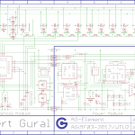
- Schematic diagram. I know I should be using more labels, but I really like having everything compactly in one rectangle. I’ll probably produce a more human-readable version soon. :/
-
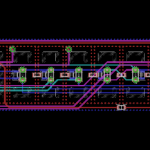
- Board layout. Because of the small size requirements, I had to take some… er… creative liberties (like soldering LEDs on top of vias).
-
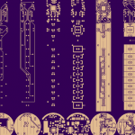
- I used OshPark, since they provide 4-layer board services for small batch orders for a reasonable price.
-
- Board from OshPark. Looks good to me.
-
- Starting to solder some components…
-
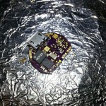
- Finished soldering most of the components for the two separate boards.
-
- Boards are connected together (right now I’m fixing a dead IC).
-

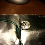
- Machining a heatsink for the LED.
-
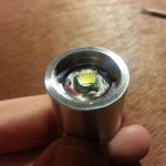
- Completed heatsink with the LED (which also has a small heatsink) inserted.
-
- The reflector fits snuggly over the LED and inside the heatsink.
-
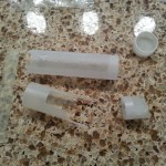
- 3D-printed prototype case parts.
-
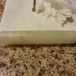
- Prototype case, mostly assembled. The screw-tail cap also works! Unfortunately, the tiny fastening screws don’t.
-

- Programming in bed.
-
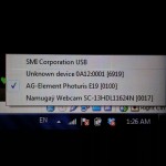
- Windows detects my flashlight as an HID device!
-

- Programming on the plane back home.
-
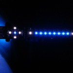
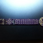
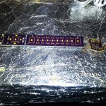
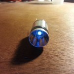
- Close-up of the display LEDs.
Also, here’s what the driven LED looks like. Right now I’m getting peak currents around $2.5A$ (just under the LED max current rating).