At my high school, TJHSST, all freshmen take “IBET” – integrated Biology, English, and Technology. One of the last projects we did for the “technology” portion was a robotics competition. In this competition, all of us were given two servos, a PICAXE board, and a few additional components, then we had to design a case for the robot, as well as put together the PICAXE board, the servos, the wheels, etc, to make a functioning robot. Finally, we had to program the PICAXE chip to control the robot. The challenge/goal was to get around a maze of obstacles.
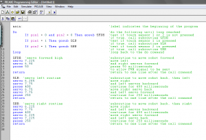
Actually, even before working on the robots, we had to learn the PICAXE BASIC programming language… which took a total of 5 minutes… Anyway, here’s a simple BASIC code example (no pun intended).
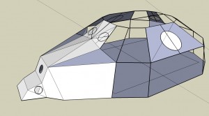
I don’t even know why I put so many comments in… maybe it was something I had to turn in? So coding the robot turned out to be fairly simple. The hard part was the actual physical construction of the robot. So essentially, I wanted a shape that could have a lot of storage, but would require a minimum amount of surface material… a sphere! To make it look like something, I decided I might as well make it look like a ladybug. So I went out to design a 3D figure. This 3D model is what I came up with (made on Google SketchUp).
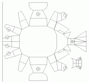
Of course, this was only for designing purposes. The usefulness of the 3D model was that I could measure all the side lengths, to then create a 2D CAD file:
As you can see, it was a fairly complicated design. It’s at this point that they told me I had to hand cut everything (despite the fact that we have a laser cutter that takes CAD files…). Well, this was fairly disappointing, especially considering how many pieces I would have to cut… oh well…
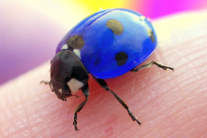
Now I had a choice of black, blue, and red plastic. And of course, since I decided to make a ladybug, I chose blue as the case color. What? Ladybugs are blue!
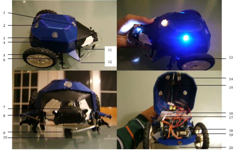
Now I don’t have any images of the construction process, because I didn’t bring a camera to school. But I do have diagrammed images of the final result.
The parts of the ladybug-robot are:
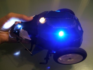
- The RGB flashing light is an indicator that the robot is on, but other than that, serves no functional purpose. Its main purpose is for the design aspect of the challenge. The RGB LED can be seen lit (with the R & G on = Yellow) in the top right image.
- The rear LED’s are red and turn on whenever their side servo is propelling the robot backwards. The purpose of these lights is to show when the robot hits a wall (since it will back up and those red LED’s will light).
- The middle LED’s are blue and turn on whenever the side servo is going the correct direction to propel the bot forward. These lights don’t serve much functional purpose, but they are useful for design purposes. The blue lights can be seen lit in the top right image.
- The body of the bot is made of PVC plastic and bent to conform to the shape of a ladybug. Its purpose is for structure and holding all the parts together.
- The wheels are rubber LEGO wheels that allow for great traction, speed, and predictability. Together with the gear system and servo, they make the robot move.
- The legs used to have wheels on them for a purpose, but the newer back wheels were too big, so the front wheel didn’t contact the ground. Therefore, the legs are merely for its look.
- The white LED serves as a flashlight for the robot, even though it will not need the extra light. The LED might be used in conjunction with the photodiodes eventually, but probably not for this competition.
- The photodiodes are mainly for design right now, since they are not being used, but eventually, they could be used.
- The front sensor “whiskers” can sense objects that contact them head-on or slightly at an angle.
- The front wheel allows the robot to move straight forward, instead of at a slant, which could occur from just a piece of plastic. Also, it lowers friction and allows the bot to move faster.
- The actual switch is located at the “thorax” of the bug, but the clip extending from it is what normally gets pressed. The extreme leverage allows slight forces to trigger the switch.
- To fix the problem of peripheral sensing, an attachment was made that stretches across the width of the bot. If pressed, the end will press the switch.
- This is a photo of the bot in action (the wheel is spinning – causing the blur).
- A magnet at the bottom of the wing attaches to a magnet at the base (20), allowing both sides of the wing to snap closed.
- Magnets on either wing shut together, attracting both wings to each other. The wings can be separated, but the magnets help maintain the correct wing shape.
- Brass hinges replaced tape that was previously used. The brass hinges allow for sturdier support of the wings.
- Two 3.7v, 2400mAH Li-Ion cells in series provide the power for the robot. Li-Ions were chosen because they have a very high storage density, they are relatively light, they can provide high current output, and they can provide high current for a long time. Technically, the battery could supply 7.4v @ 2.4A for an hour, but the current usage for this application is much less. The fact that their voltage is lower is arbitrary, since the input voltage is regulated to 5v anyway, so the max voltage really needed is around 6.5v.
- The PICAXE and board controls all the parts and is the brain of the robot, much like my PIC controls my flashlight.
- The gear connected to the servo is seen through a hole in the PVC. The number of teeth on the gear is 24, where the other gear has eight teeth, and is connected to the back wheel.
- This magnet attracts the magnet on the wing (14) to snap the wing down.
I actually spent a lot more time in making this robot than many others did because I bothered to gear up the servos (as well as bypass the 5v regulator to give the servos more power). Anyway, I ended up getting about 3rd place in the school with this robot, although I should point out that the competition was largely up to chance, as I would sometimes get 50 points, and sometimes over 150 (where more points are given for hitting more unique obstacles).
Also, I was required to complete documentation of this robotics project, so if you’re interested…
