Construction
Construction of the AGMF Flashlight was much simpler than that of the AGXF Flashlight, especially since it had much fewer parts than the AGXF. The main components were the Cree XP-E LED (R2), the lighted DPDT latching switch, the IR receiver, the microcontroller, the power transistor, and the 10280 Li-Ion cell.
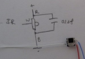
I started by building small modules that would eventually be combined to create a larger module. Here’s the IR module which included the attached wires and the $0.1 \mu F$ capacitor.
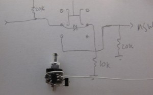
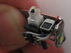
The next module was the lighted DPDT switch. You can see the (very) small SMD LED at the top of the switch, as well as the aluminum foil that acts as wires down to the switch contacts. On the side of the switch, I’ve already attached the programmed MCU, as well as the power transistor.
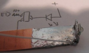
The most important module is the Light module. It consists of a piece of bent copper “tinned” with solder and soldered to a Cree XP-E R2 LED. Near the bend, I’ve also soldered a thermister, which allows the microcontroller to determine if the LED is too hot, based on its resistance.
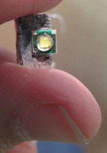
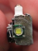
Looking at the front of the LED module, you can see that the XP-E LED is very small (compared to my thumb). I think it was about 5mm square.
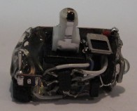
Combining the modules we’ve seen so far, we get the AGMF Head. Note how everything has been placed to allow for the whole head to be inserted into a tube. The head isn’t completely finished though.
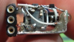
First, I had to add the female headers as seen on the left of the head. Then, to secure everything in place, epoxy secured all the components together. You can also see that the copper “heatsink” has been trimmed to match the size of the head.
…the front view of the head…
…the bottom view…
