Construction
While coding was certainly the hardest and most time consuming part of this project, construction was no simple feat either. As you could see from the parts list above, there were over 75 parts that needed to be crammed inside a $\frac{1}{2}$” I.D., $4$” long clear acrylic tube. In fact, the only way this was possible was to use extremely tiny SMD components (0603 sized – 0.06″ x 0.03″). Unfortunately, I don’t have very good documentation of me actually constructing the flashlight. In fact, I really only have 2 pictures of the construction process.
Here’s a picture of an etched PCB board containing three copies of the circuit I used for my flashlight. As usual, I made this PC board by printing the artwork onto a sheet of paper in a laser printer, transferring the toner onto the blank PC board by ironing, and then etching the board using Ferric Chloride. The left one has already been cleaned of toner and “tinned.”
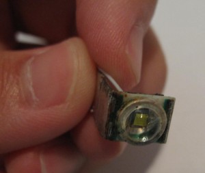
And here’s the main LED module. It consists a Cree Q5 White LED soldered onto a piece of copper (serving as the heatsink). Near the bend in the copper, I’ve also soldered an NTC thermistor. This component allows the MCU to tell when the LED is too hot, thus allowing the MCU to reduce the duty cycle of the LED.
Well, that’s pretty much all of the photos I have of the construction process. The actual process took about two weeks to complete, although I think a total of less than 50 hours were spent on construction (as opposed to 200 or so hours for coding).
Final Pictures
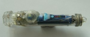
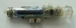
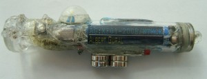
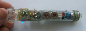
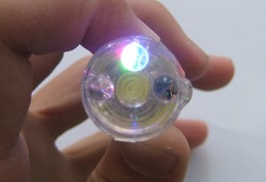
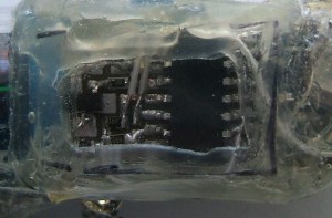
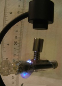
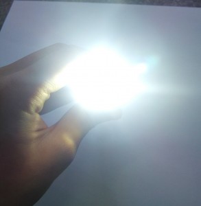
Here are some final images of my flashlight.
|
|
|
If you’re interested, a LOT more information about this flashlight can be seen on some documentation I made a while ago (although it’s still fairly incomplete).

