With the basic plan for the flashlight complete, I now had to decide on
exactly what parts to use, as well as figure out the wiring of the system. I spent a while looking through all sorts of electronics stores until I finally completed a list of all the components I needed. One of the hardest parts was actually figuring out what microcontroller to use. After figuring out that I’d need about 12 I/O pins (thus, a 14-pin MCU), I found the PIC 16F684 microcontroller fit my needs pretty nicely. It had nice peripherals, such as ADCs (analog-to-digital converter), PWM (pulse-width modulation), and 2K memory. Decent enough for my needs.
Here’s a (probably non-comprehensive) listing of these items:
Electronics
- (1) PIC16F684 (SMD)
- (1) Li-Ion Cell
- (1) CREE XR-E Q5 LED
- (1) DPDT latching pushbutton switch
- (3) .2” sq switches
- (1) IR LED
- (1) RGB LED
- (1) UV LED
- (1) Small Speaker
- (1) 5mm Reed Switch
- (1) 1.5A PTC resettable fuse
- (7) Female DIP sockets
- (1) IC switch TS5A3166
- (1) Li-Ion charger STC4054
- (2) SOT-23 NPN transistors
- (1) IR sensor TSOP34838
- (1) 10KΩ (25oC) NTC thermistor
- (2) 1uF capacitors [603,603]
- (1) R,G,B LED SMD (1210)
- (3) Red SMD LED [1206,603,603]
- (1) Orange SMD LED [603]
- (2) Yellow SMD LED [1206,603]
- (2) Green SMD LED [1206,603]
- (3) Blue SMD LED [1206,1206,603]
- (2) White SMD LED [603,603]
- (1) 3V Zener Diode
- (3) small ( (3) 100Ω resistors [603,603,603]
- (1) 220Ω resistor [1206]
- (2) 470Ω resistor [1206,1206]
- (2) 1kΩ resistor [603,603]
- (2) 3.3kΩ resistor [603,603]
- (1) 3.9kΩ resistor [603]
- (1) 4.7kΩ resistor [603]
- (2) 10kΩ resistor [603,603]
- (1) 18kΩ resistor [603]
- (3) 20kΩ resistor [603,603,603]
- (2) 22kΩ resistor [603,603]
- (1) 27kΩ resistor [603]
- (2) 100kΩ resistor [603,603]
- (1) 1MΩ resistor [603]
|
Casing
- Acrylic tube .5”ID x .625”OD
- Epoxy
- Glue gun glue
- Clear Silicone RTV
Misc.
- Silicone Putty
- 2-part clear casting urethane
- Wire-wrap wire (30 gauge)
- Solder
- Indalloy 117
- PCB (see layout)
- (4) magnets 1/8”ID x 3/8”OD x 1/8” thick
- (2) magnets 1/16”ID x ½”OD x 1/16” thick
- ¼” spherical bead
- 5mm cubic zircon
- Red, Yellow, Blue, White, Black Acrylic paints
- Warning, XF, owner, contact labels, laminated
- Straw
- Thermal Compound
- Silicone Cap
- Magnetic LED leads
Tools
- Glue gun
- Soldering Iron
- DREMEL tool with circular diamond saw
- Needle-nose pliers
- Wire strippers
- Wire cutters
- Ruler
- Tape
- Holding implements (helping hand)
|
Now that I figured out what components to use, how would I wire everything up? It actually turned out to be fairly easy, using the MCU as the heart of the whole system. As it turned out, only some pins could be used for PWM, while some others worked with ADC. I could narrow down which pins went to which “modules” of the flashlight.

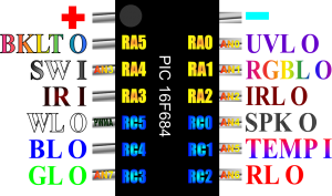
MCU Pin Destinations
From pin 1 through 14, the destinations were: positive supply, backlight system, switch input pin, IR LED, main Cree Q5 White LED, blue status light, green status light, red status light, LED temperature probe, speaker output, IR receiver input, flashing RGB LED, UV LED, and ground. With that done, it was not too difficult to design the circuit.

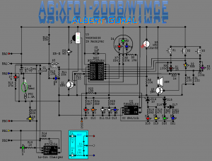
AG:XF01 Schematic Diagram
At first glance, it looks a little bit complicated, but really, it’s just 12 or so modules stuck together to the appropriate MCU pin. As always, it’s very well colored (for no reason, except readability – colors make it easier to distinguish similar objects, and partially gives a better understanding of what the component does).
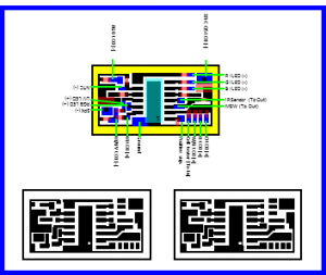
After completing the schematic diagram, I could also work on yet another PCB. As I had done before, I completed the PCB layout in PowerPoint, except this time, the PCB had to accommodate SMD-sized components.

PCB Layout


